Difference between revisions of "Steam turbine example"
(+cat) |
|||
| Line 82: | Line 82: | ||
* Reduce the use of rheostats to regulate the speed of the shaft by having better inflow regulation | * Reduce the use of rheostats to regulate the speed of the shaft by having better inflow regulation | ||
* find a sweet spot between steam turbines and generators - how many generators to a turbine? | * find a sweet spot between steam turbines and generators - how many generators to a turbine? | ||
| + | |||
| + | [[category:Example]] | ||
Revision as of 01:17, 28 November 2017
Contents
Basic Steam Turbine
Here's a simple example (perhaps a first tier with the raw essentails) of what is needed to make a steam turbine work :)
Obviously, as your power needs increase, this basic solution may not suffice any longer, at which point, you may need to work on better regulation with PID's for example.
But, this is great for your basic setup.
What you will need to get started
- 1.2 buckets per second (or 80mB/t - Gold BuildCraft Fluid Pipe for example) of Steam - I tend to use Railcraft steam
- 1x Steam Turbine
- 1x Signal Trimmer
- 96+ Coal Dust - used to configure Rheostats resistance. (One can reduce this requirement a little bit by using more signal trimmers on the signal lines for the rheostats, it saves a few dust)
- 1x Tachometer
- 1x Signal Cable
- 1x Very High Voltage Relay
- 2x Large Rheostat (the one with a heat sink)
- 4+ Small Passive Thermal_Dissipator - or better. You don't need as many of these if you have active dissipation
- 1x Ground Cable
Also recommended
- Some Very High Voltage Wire (at least 12 probably)
- Circuit Breaker (two or more best, one at the inflow, and one at the output)
- Enough DC/DC converters and respective cables and cores for them to reach the desired voltage
- Electrical Probes and loggers (for watching your power over time)
- Somewhere to dump all of this power (but not essential)
Layout
Below, find a minimal example of a steam generator.
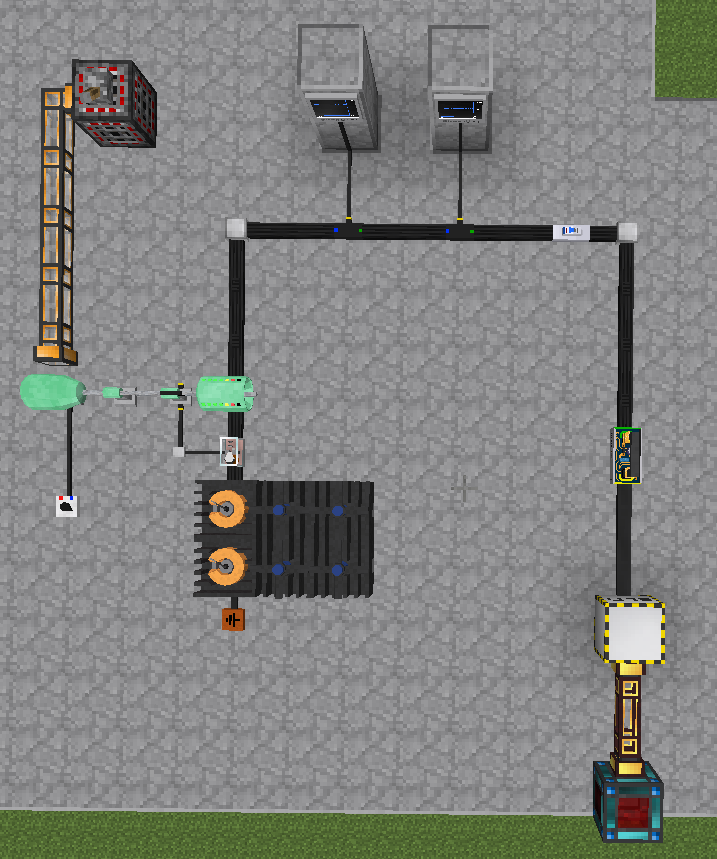
Starting from the upper left, we have a Ralicraft admin steam producer. This can produce ridiculous amounts of steam, which we then pipe into the steam turbine. The steam turbine has a signal trimmer set at 16%, which allows approximately the same as a gold BuildCraft pipe, around 1.2 Buckets/s or 80mb/t. Allowing more than that will actually cause problems and you will explode, since the resistor will not be able to regulate the power enough to prevent the axle from spinning out of control.
In general, the amount of steam you need can be produced by a 2x2 Railcraft boiler, with 2 tall high-pressure chambers. Increasing chambers will increase the steam production. Remember, keep water in the boiler or it will explode :)
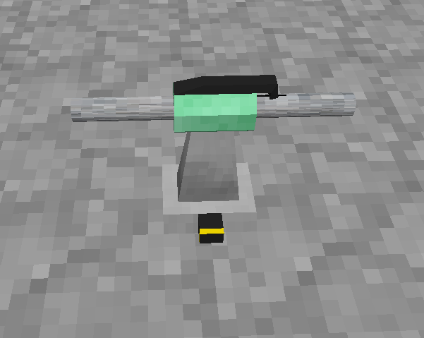
To the right of the generator, we have a tachometer:
The tachometer is configured to output 50v when the rotational speed is less than 800 rad/s, and to output 0v when the rotational speed is more than 801 rad/s. This in turn sets the relay to turn on and off (it's in the normally closed position). What this does, is when the generator goes over the designated speed, it converts the rotational energy into heat in the large rheostats, and thus slowing down the shaft rotation. It also does cause the output voltage to go down a little bit.
In the overview, you will see that there are two large rheostats, and then they ground out. The rheostats have 64 and 32 coal dust in them (ore-dict coal dust is fine), which modifies the resistance of the rheostat.
Behind the rheostats, we have heatsinks (thermal disappators). The ones in the photo are 200v active ones, but they can be passive if the temperature stays below 100C at idle. Adding more disappators allows more heat to be removed from the system as well. You can also technically get some of this power back with other means, such as the heat turbines.
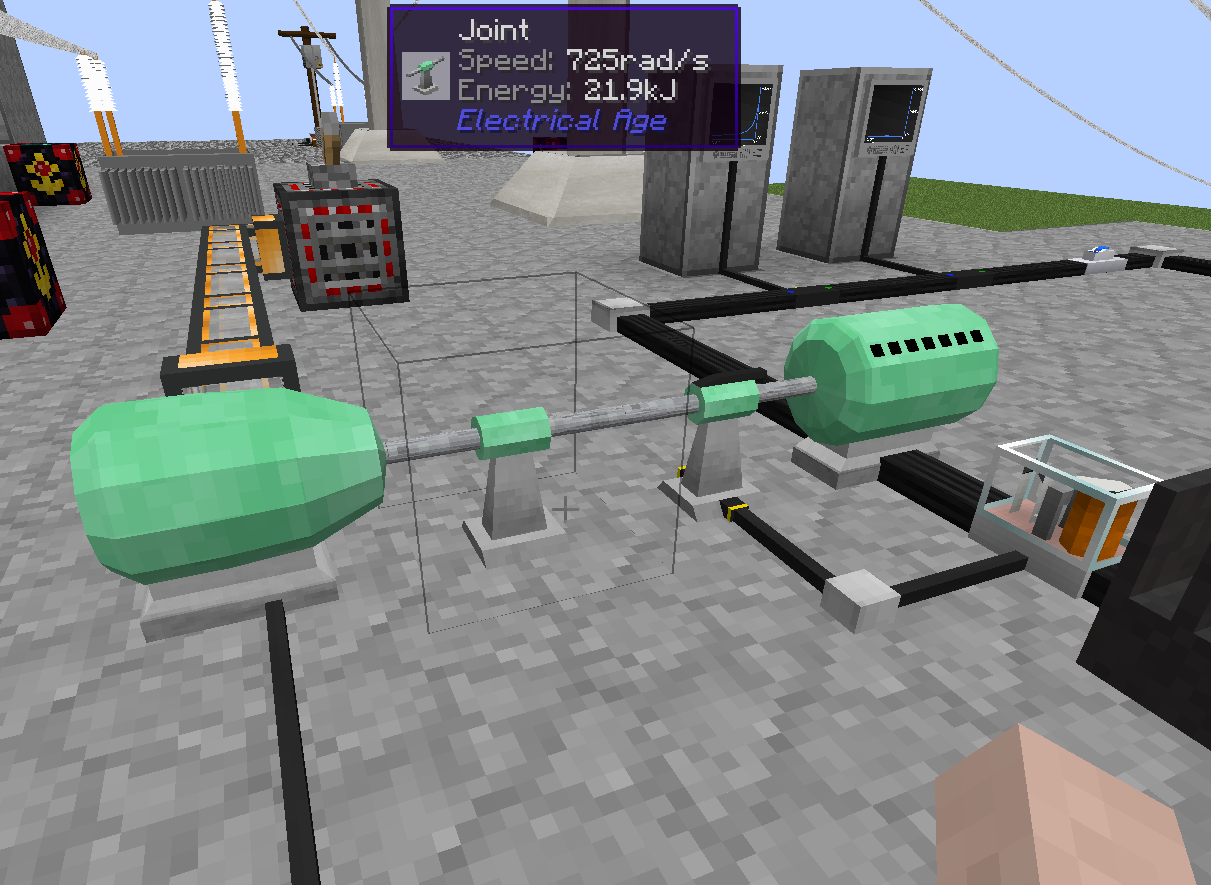
Here's a final close-up of the generator:
Monitoring, Circuit Breakers, and output example
One of the leads from the motor proceeds to go to the two panels near the upper right of the image. They monitor the voltage and watts respectively for the cable. If you right click on the screens, you can configure what they are measuring, and what the lower bound and upper bound are on the graph. You will want to configure this to be the same numbers as what is on the electrical probe, otherwise your graph will be incorrect (it's all based on the voltage from the electrical probe, between 0v-50v on the signal cable).
After that, we have an electrical breaker set for 3600v (or 3.6kV). If you go above that, then it's time to prevent the cable from exploding. It also prevents over-current draw on the cable.
In this case, our power gets dumped into a transformer to convert to 800v, and then a 800v energy converter, which fills an RF storage unit.
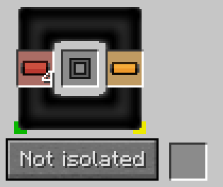
See below for the Transformer configuration. Intuitively, the VHV cable side (the green side in this case) connects to the VHV cables on the ground (also marked on the green side), as seen in the overview. The same goes for the orange cables - they are both connected to the yellow side. Since we have an optimal core, and there is a 4:1 ratio of cables, it coverts 3.2kV to 800v (4:1).
Starting the generator
As soon as you apply steam, the shaft will begin to rotate. Be prepared for this. You will want all of the electrical work in place to regulate the voltage before you start - if your shaft goes over 1000 rad/s, it will explode. It also will increase in speed in quadratic fashon after 200 rad/s..
Also worth noting that if you have power on the DC/DC regulator, and you insert wires, it may explode. Be sure that you don't get the wrong voltage wires on the wrong side.
Unlike the gas generators, you can just start steam by applying lots of steam to the turbine. It is recommended however that you start your generator much like the gas tutorial if you are short on time. It's not essential, but it can save 5-10 minutes of waiting for it to start. In general, never start the generator under load, or it will not start at all, due to very low efficiency at lower speeds.
If you have flywheels (which you don't necessarily need), you will certainly need to start it similarly to the gas turbine, and it will take upwards of 10-20 minutes to start. Flywheels have the positive effect of reducing the amount of fluctuation in your generator speed once it's started.
Going Further
Ways you can improve this generator:
- Use the PID block and the voltage output (via a electrical probe) to regulate for 3.2kV. Generally, the voltage and the shaft rotation speed are well related, and can prevent over-speed.
- Reduce the use of rheostats to regulate the speed of the shaft by having better inflow regulation
- find a sweet spot between steam turbines and generators - how many generators to a turbine?


