Difference between revisions of "Signal Processor"
m |
|||
| Line 26: | Line 26: | ||
The signal processor can be rotated by the use of a wrench. | The signal processor can be rotated by the use of a wrench. | ||
| − | + | To function, it needs a minimum amount of redstone inserted in its UI. | |
== Example usage == | == Example usage == | ||
Revision as of 02:21, 28 June 2015
| Block type: | Single |
| Powered by: | Signal Source |
| Requirements for operation: | None |
| Stackable: | Yes (64) |
Contents
Crafting
Signal Processor
Purpose
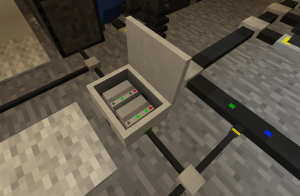
The signal processor can execute nearly arbitrary calculations on signals. It has three inputs, called A, B and C internally, and marked with colored spots on its sides. Its single output is pushed to its single black side.
Internally, it operates on floating-point numbers. Each input is mapped to the [0,1] interval, and its output is similarly capped. For example, a 10V signal line will be read as 0.2, while function "1 + A" will output 50V for any value of A. The latter is because a 0V input signal is read as 0, and negative inputs do not exist. The processor can, however, represent far larger values internally; to output these without being capped, divide them by some large number.
The signal processor can be rotated by the use of a wrench.
To function, it needs a minimum amount of redstone inserted in its UI.
Example usage
Exact code will not be included, as figuring it out is half the fun. To simplify that process I would recommend prolific use of data loggers.
Things you should be able to do with the signal processor include:
- Controlling a bank of generators, microwave receivers or similar devices to maintain an exact system voltage.
- Calculating the open-circuit voltage of a battery, given closed-circuit voltage and power use.
- Keeping a bank of batteries charged, without blowing them up.
- Tracking power usage.
- And much more...
Functions
Arithmetic
The +, -, *, and / operators are all supported, and work as expected.
Boolean operators
The >, <, &, |, = and ^ operators exist. These operate by reading any value less than 0.5 as "false", 0.5 or larger as "true". So, for example, 0.3 | 0.7 = 1, while 0.3 & 0.7 = 0.
Functions
if(a, b, c): If a >= 0.5, this returns b; otherwise, c.
min(x, y), max(x, y): Respectively, the smaller or larger of x and y.
sin(x), cos(x): Performs trigonometry, interpreting x as radians.
abs(x): Turns any negative number positive.
batteryCharge(x): Returns the battery charge, given the open-circuit voltage of a battery as expressed as a fraction of its nominal voltage. For example, given a 50V battery, you should use batteryCharge(1) if the voltage is 50V. Since the maximum input of the signal processor is 1, this necessarily means re-scaling the input to get the full range of voltages.
Procedures with memory
ramp(period): Generates a sawtooth wave, at the given period.
rs(reset, set): Initially returns 0. When set is asserted—set to 0.6 or higher—it begins returning 1, and will maintain this return value until reset is asserted, at which point it returns to 0.
integrate(value, resetTrigger): Sums "value" over time, and returns the sum. Resets if resetTrigger is asserted.
integrate(value, min, max): Sums "value" over time. Will never return values outside of its min/max bounds; its internal counter is bounded to these values. Does not have a reset trigger.
derivate(value): At each tick, returns the difference between the current and previous tick.
rc(tao, value): Returns the moving average of "value" across the last "tao" seconds.
pid(target, hit, p, i, d, minV, maxV): Returns min(minV, max(maxV, pid(target, hit, p, i, d)))
pid(target, hit, p, i, d): This implements a PID controller. See below.
PID Controller procedure
The pid procedure is a standard implementation of a Proportional-Integrate-Derivative controller, as can be found described on Wikipedia. Given pid(target, hit, p, i, d), the procedure attempts to manipulate its output such that the values of target and hit become equal.
The p, i and d parameters control the three procedures used to accomplish this; you can adjust them to adjust how much each contributes to the controller's output.
The PID controller assumes that its input (hit) is a monotonic function of its output, and may malfunction if this is not the case, though it is relatively robust to complex functions and lag between changing output and input.
For more details you should really read the Wikipedia entry on PID controllers, but a quick overview:
The PID controller starts by computing the "error", as "target - hit". It then computes the P, I and D functions, sums them, and returns the sum.
P: This is a simple function, which returns "error * P". Given a perfectly proportional system, it may be all that is needed; usually it is not.
I: This sums (error * I) over time, and outputs that. As the sum can only decrease if the error is negative, some overshoot is guaranteed, but using it is usually required to avoid offsets from the correct output. It is somewhat vulnerable to integral windup, but the internal sum is capped to (-1, 1), which limits this.
D: This returns the derivative of the error, multiplied by D. This allows the controller to react to how fast its output is changing, and can be used to limit overshoot.
For more tips, see the "Manual Tuning" section on Wikipedia.
